The multiverse – creating universes in Blender
I created the image above for an article in the magazine "Spektrum der Wissenschaft", about the multitude of possible parallel universes in hyperspace, in 2009. At that time I didn't know about Blender, but I wanted to create real 3D objects and so I used Corel Dream 3D version 7.0 for that (oh yes, I can hear you sigh ...). This software had some bugs and is not supported anymore. Today's (free) tool of choice for tasks like this is Blender. Want to know how that works? Feel like creating your own universes? Just go ahead and follow the instructions below.
If you like the scroll-parallax effect, which makes the universes here fly upwards and look somewhat similar to sky lanterns, jump directly to the last section on the parallax effect.
1. Setup
Prerequisites
You need Blender version 2.7 or higher, since it contains the "Screw" modifier which we can use for creating rotation bodies from a curve, without destroying the original curve. So the bodies can be modified even after they have been created.
I am assuming that you have some basic knowledge on how to select (right mouse click), move (G) and rotate (R key) objects, how to switch between Object and Edit mode (Tab key), how to customize your window layout, where and how to assign materials to objects etc. If you are a beginner in Blender, have a look at blender.org first and go through some basic tutorials.
Collect nice images of the universe that you can use as textures. This can be anything from nebula to star fields and galaxies. NASA offers a lot of pictures for free which are perfect for our purpose. But you could also paint your own of course or use results from cosmological simulation images, for example from the CosmoSim webpage.
Prepare the scene
Start Blender and delete the default cube. Select the default Camera (right click), then move it to a new position: (X,Y,Z) = (0, -20, 3.45). This can be done using the properties panel (enable with N key) in the 3D view window. Clear the rotation of the camera (Alt+R and set the X rotation angle to about 84 degrees. Now the camera looks along the Y-axis from slightly above.
Select the camera. Then switch to the Properties window to adjust the camera settings. Make sure that the Lens is set to Perspective. Set the Focal Length to about 60.0. Increase the Sensor Size to 100.0 (or move the camera further away) to get a bigger view on your scene.
In Properties window, select the World tab. Adjust the World color, e.g. choose Blend Sky, Horizon Color: 0.45, 0.78, 0.202 and Zenith Color: 0.10, 0.10, 0.10. Check "Environment Lighting" and set Energy: 1.000 to ensure that your objects will be visible as if they are placed in daylight. Also check "Mist", set Start: 15.00, Depth: 60.00 and Falloff: Linear. This will give far away objects a misty appearance, as if there was some kind of atmoshere.
We still want some light-and-shadow effects, so select the default Lamp (or add a new one) and adjust its position: -60, -30, 3 (somewhere to the left and above the default plane). In Properties window, set the Lamp: Sun and its Energy: 0.200. Play with these settings to get stronger shadows or brighter speculars for your objects later on.
Create the grid plane
If you want to put your universe shapes on a plane with grid lines, then choose Add -> Mesh -> Grid. For a picture similar to the one above, set the number of X and Y Subdivisions to 200 and the Radius to 75. Place the plane below your universes.
In the Properties window, add a material to your plane by clicking on Material tab, New. Adjust the material as you wish (you can also turn it into a dark reflecting mirror, for example!). For now, we just set the Diffuse color to black (0,0,0) and Specular Intensity to 0.
Add a second material with a different color (e.g. (RGB) = (0.184,0.086,0.110) ) to the plane, which will be used for the grid lines.
Now add the grid lines: still in Properties window choose Modifier tab, Add Modifier -> Wireframe. Set Thickness: 0.0200 and Material Offset: 1. This assigns the second material of the plane to the grid lines. Uncheck "Replace Original" to have both, the plane AND the grid lines visible.
2. Add a single universe shape
Create a rotation object
Add a Bezier curve: in 3D View choose Add -> Curve-> Bezier. By default, the curve will be parallel to the X-Y-plane, but we want it in X-Z-plane. Thus rotate the curve around the X-axis by 90 degrees (R, X, 90). Important: Apply the rotation now with Object -> Apply -> Rotation, so that you won't run into troubles later on with the Screw modifier. This resets the rotation angles to 0,0,0, but keeps the current orientation of the object.
In Edit mode, switch to front view (Num 1) and modify the curve so that it represents half the outline of your shape. You can add more control points using Extrude (E) from an endpoint of the curve or by selecting two points (hold Shift key to select two points) and using Subdivide (Curve Tools in the left panel of the 3D View window or Curve -> Segments -> Subdivide). Note that you can adjust the handle type for each curve point individually. E.g. in order to make a "spike" (sharp edge), select the point, then choose Curve -> Control Points -> Set Handle Type -> Vector.
The following screenshot shows some example curves:
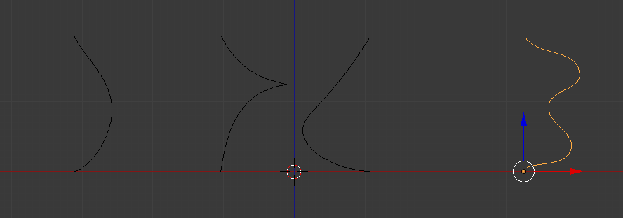 Note: If you want to have a closed object in the end, make ensure that the first and last point of your curve have the same X-values.
Also ensure that the curve is flat, i.e. it's still in a plane parallel to X-Z-plane, all Y-values of your control points must be the same. You can check that best by switching to Top view (Num 7) and checking that the curve appears as a straight line parallel to the X-axis. (If you worked on your curve in front view (Num 1), this should be no problem.) If your curve is not flat, you can just set the width in Y-dimension to 0 (properties panel of 3D View (N)).
Note: If you want to have a closed object in the end, make ensure that the first and last point of your curve have the same X-values.
Also ensure that the curve is flat, i.e. it's still in a plane parallel to X-Z-plane, all Y-values of your control points must be the same. You can check that best by switching to Top view (Num 7) and checking that the curve appears as a straight line parallel to the X-axis. (If you worked on your curve in front view (Num 1), this should be no problem.) If your curve is not flat, you can just set the width in Y-dimension to 0 (properties panel of 3D View (N)).
Before applying the Screw modifier for creating the 3D shape, we need to place the origin of the curve right at the bottom of the object: Switch to Edit Mode, select the down-most point, then use Shift+S to open the Snap menu and choose "Cursor to selected". This puts the 3D cursor at the same position as the down-most point. Now switch back to Object mode, choose Object -> Transform -> Origin to 3D Cursor, and the origin of the object is now aligned with the down-most point of your curve.
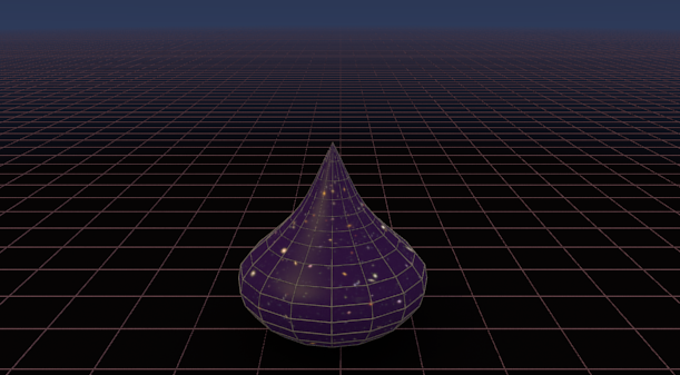
Now you are ready to use the Screw modifier: with your curve selected, go to the Properties window, Modifier tab, click on "Add Modifier" and choose "Screw". With the default settings (Axis: Z, Screw: 0, Angle: 360°), this should already create a rotation body, as if your bezier curve was rotated around the Z-axis through its origin, see the image below.
 You just created a 3D object from your curve, and the best thing is: you can still adjust your curve in Edit mode – and the 3D shape will adjust as well!
Increase the resolution of your object by increasing Render Step (and Step; default: 16), if you want a smoother object.
You just created a 3D object from your curve, and the best thing is: you can still adjust your curve in Edit mode – and the 3D shape will adjust as well!
Increase the resolution of your object by increasing Render Step (and Step; default: 16), if you want a smoother object.
Add material and textures
Select your curve, switch to the Properties window again and go to the Material tab. Click "New" to add a new material. Change the diffuse color, e.g. to (RGB) = (0.561, 0.129, 1.000) for a light magenta. Increase the Diffuse Intensity to 1.0 and lower the Specular Intensity to 0.1. You may also want to decrease the Specular Hardness to about 25 to make it less prominent. At the Shading section, set Emit: 0.55 to give your shape a "glow-from-the-inside" effect.
Switch to the Texture tab and click New to create a new texture for your object. The default Type is "Image or Movie" which is perfect for our needs. Scroll down to the Image section and click "Open" to select an image of your choice, e.g. the Hubble Ultra Deep field. Scroll down to the Mapping section and set Coordinates: Generated, Projection: Sphere. This defines how the texture is wrapped around the object and should work as expected for most of your shapes. Experiment with this and consider using the more advanced UV-mapping for even more control and better results.
Scroll even further down to the Influence section. "Color" is already checked, but lower the value slightly to 0.97. This has the effect that the glowing color still shines through the texture. You're nearly done!
Add grid lines to your object
There are different ways to achieve this in Blender, each with its advantages and disadvantages. You could follow the same steps as for the big grid plane, using a Wireframe modifier. Unfortunately you would need to convert the curve that defines your universe shape into a mesh beforehand (Alt+C, or Object -> Convert -> Mesh from Curve/Meta/Surface/Text). This destroys your original curve, but
you can get a wireframe grid with easily adjustable line thickness etc. Here's an example, the with Thickness: 0.0500 and Relative Thickness enabled:
The wireframe lines represent the lines of the underlying mesh, and thus they are straight lines between vertices, as can be seen in the picture above. I prefer them to be smoother. One easy way to achieve this, is using an image with grid lines as additional texture. I used the following image, which contains 10 lines per dimension, and it's seemless, i.e. it can be repeated in each direction without a visible break in the pattern.
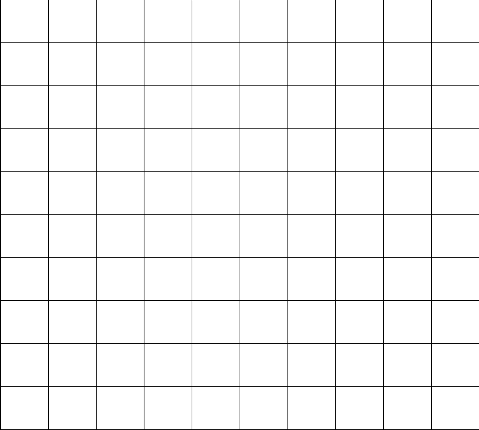
Add another Image texture to your object and open the grid file as texture image. Adjust the color, if necessary, e.g. for light brown grid lines (good on dark background!), set (RGB) = (1.5, 1.4 , 1.0) and Brightness to 1.6. Scroll doen to the Mapping settings and set Coordinates: Generated, Projection: Sphere, just the same as before. You may want to adjust the Offset and Size of the grid image, so the number of grid lines and their position suits your needs. For the example below I chose Offset: Y: -0.05, Size: X=0.90, Y=0.80. I also set the Color at Influence to 0.30 to make the grid lines more decent.
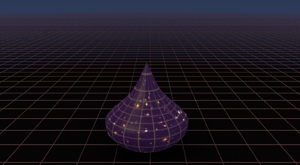 The result looks already quite good and very similar to one of the shapes in the original image. The grid lines are a bit too much stretched at the top, but at least they look smooth and – best of all – the underlying curve is still preserved and can be modified any time.
3. Finish
Add more shapes
Create as many different shapes with different textures as you want and place them in your 3D scene. Use the Top view (Num 7) to place the objects and check in Camera View (Num 0) how they are seen from the camera. When you are happy with the result, adjust the resolution in the Properties view, Render settings and render your image (F12). That's it!
Final touches with Gimp
When I created the image initially, I wasn't happy with the background yet. But luckily there is Gimp, a free tool similar to Adobe Photoshop for editing images. I opened the image in Gimp, added a new layer and created a gradient from dark blue to transparent from the top of the image to about its center. I put this on top of the original image and exported this as the final image. You can also use Gimp to adjust colors, brightness, contrast etc. of your final image. By the way, Blender also offers possibilities like this, but that's a more advanced topic. Search for "Blender" and "Compositing" in the internet to find out more about after-render-editing in Blender.
Want your image for the web? – The parallax effect
You want more than a still image for your webpage? A parallax-scrolling effect like on this site? Once you have set up your image in Blender that's easy enough to achieve. You need to split the image into a number of layers (for the image at the top I used 14 layers). You can hide each object for rendering in Blender by clicking on the eye-symbol next to each object in the Outliner window. Hide all objects, then make only the foreground objects visible for rendering, render the image (F12) and save it. Then hide the just rendered foreground objects, make objects directly behind them visible, render them, hide them, show the next row, render etc. etc. This way you create layer images with each layer containing a deeper part of the image. Now you need to assign different positions when scrolling for each layer, using CSS transformations and a bit of javascript. I followed the advice in this tutorial which gives very good explanations and a working example for this multi-layered parallax effect: Tutorial: Multi-layered parallax illustration.